8강. IR Sensor 제어하기
HeaderPin         GPIO

  1               I38
  2               I37
  3               I35
  4               I34
이렇게 소켓들을 연결합니다.
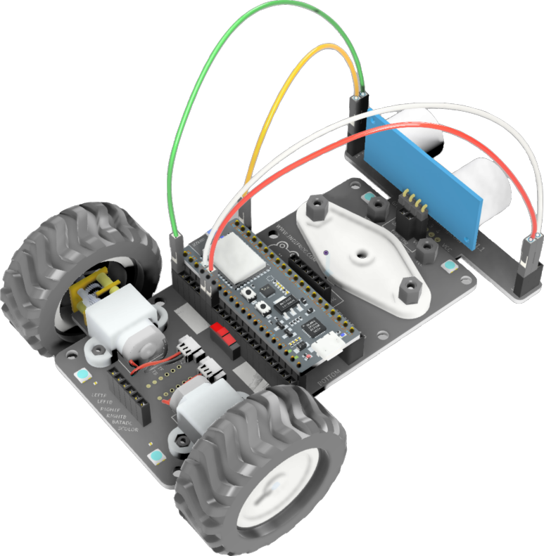
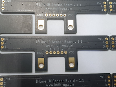
IR 센서를 설계할 때, 보드의 크기와 센서내부 간섭을 최소화하기 위해 IR발광부, 수광부가 통합된 고가의 센서를 사용했습니다.
IR 센서보드에는 4개의 센서가 있고 OpAmp 비교기는 포함하지 않았습니다.
OpAmp 비교기를 추가하게 되면 인터럽트 처리를 할 수 있기 때문에 상당히 빠른 응답 결과를 얻을 수 있는 장점이 있으나 실제 사용할 때, 가변 저항을 이용해서 기준 임계 전압 값을 조절해야 하는 번거로움이 있기도 하고(공통) 미세 조정을 하는 것이 쉽지 않습니다.
물론, 장소와 시간에 따라서 외부 빛의 세기에 따라 IR수신 센서가 영향을 받을 수 있어 미세 조정이 필요하긴 합니다만, iFLne은 이러한 상태가 어느 정도 균일한 실내를 기준으로 라인트레이스를 한다고 가정을 하고 있습니다.
그래서 ESP32의 빠른 스피드를 최대한 살리면서 ADC의 정교함을 이용하는 것이 보다 더 효율 적이라고 생각해서 구현한 것입니다.
위 그림의 하드웨어는 PP버전이라서 최종 양산 버전에서는 1, 2번의 내부 위치가 변경되었음을 알려드립니다.
아울러 VCC, GND의 위치도 IFLine의 앞쪽으로 배치가 되었습니다.
1
2
3
4
5
6
7
8
9
10
11
12
13
14
15
16
17
18
19
20
21
22
23
24
25
26
27
28
29
30
31
32
33
34
35
36
37
38
39
40
41
42
43
44
45
46
47
48
49
50
51
52
53
54
55
56
57
58
59
60
61
62
63
64
65
66
67
68
69
70
71
72
73
74
75
76
77
78
79
80
81
82
| #include <Arduino.h>
#include "driver/adc.h"
#include "esp_adc_cal.h"
static const adc_atten_t atten2 = ADC_ATTEN_DB_6;
static esp_adc_cal_characteristics_t adc_chars;
#define DEFAULT_VREF2 1100
#define IR_SENSOR_1 GPIO_NUM_38
#define IR_SENSOR_2 GPIO_NUM_37
#define IR_SENSOR_3 GPIO_NUM_35
#define IR_SENSOR_4 GPIO_NUM_34
int analogRead(int pin){
adc1_channel_t channel = ADC1_CHANNEL_1;
switch( pin ){
case IR_SENSOR_1:
channel = ADC1_CHANNEL_2;
break;
case IR_SENSOR_2:
channel = ADC1_CHANNEL_1;
break;
case IR_SENSOR_3:
channel = ADC1_CHANNEL_7;
break;
case IR_SENSOR_4:
channel = ADC1_CHANNEL_6;
break;
}
int read_raw = adc1_get_raw((adc1_channel_t)channel);
return read_raw;
}
void initAnalogPins(){
pinMode(IR_SENSOR_1, INPUT_PULLDOWN);
pinMode(IR_SENSOR_2, INPUT_PULLDOWN);
pinMode(IR_SENSOR_3, INPUT_PULLDOWN);
pinMode(IR_SENSOR_4, INPUT_PULLDOWN);
adc1_config_width(ADC_WIDTH_12Bit);
adc1_config_channel_atten((adc1_channel_t)ADC1_CHANNEL_6, atten2);
adc1_config_channel_atten((adc1_channel_t)ADC1_CHANNEL_7, atten2);
adc1_config_channel_atten((adc1_channel_t)ADC1_CHANNEL_2, atten2);
adc1_config_channel_atten((adc1_channel_t)ADC1_CHANNEL_1, atten2);
esp_adc_cal_value_t val_type = esp_adc_cal_characterize(
ADC_UNIT_1,
atten2,
ADC_WIDTH_BIT_12,
DEFAULT_VREF2,
&adc_chars);
}
void setup() {
initAnalogPins();
}
void loop() {
int irLeftR = analogRead( IR_SENSOR_1 );
int irLeft = analogRead( IR_SENSOR_2 );
int irRight = analogRead( IR_SENSOR_3 );
int irRightR = analogRead( IR_SENSOR_4 );
printf("irLeftR = %d, irLeft = %d, irRight = %d, irRightR = %d\n", irLeftR, irLeft, irRight, irRightR);
}
|